תרגומי מונחים מקצועיים
| עברית | אנגלית | עברית | אנגלית | |
|---|---|---|---|---|
| מטיל | bar, ingot | סנטור | sintering | |
| חישול, כבישה | forging | פילט | fillet | |
| חישול בטבעים (סגורים) | impression-die forging, closed-die forging | פלאש | flash | |
| חישול חופשי | open-die forging | חריטת מצח, חריטת אורך | face turning, straight turning | |
| ערגול | rolling | |||
| שיחול | extrusion | |||
| משיכה | drawing |
Metal Casting
From (Kalpakjian & Schmid, 2016):
Several methods can be used to shape materials into useful products. Casting is one of the oldest methods and was first used about 4000 B.C. to make ornaments, arrowheads and various other objects. The important factors in casting operation are:
- Solidification of the metal from its molten state, and accompanying shrinkage.
- Flow of the molten metal into the mold cavity.
- Heat transfer during solidification and cooling of the metal in the mold; and
- Mold material and its influence on the casting operation.
Cast Structures
The type of cast structure developed during solidification of metals and alloys depends on the composition of the particular ally, the rate of heat transfer, and the flow of the liquid metal during the casting process.
Pure Metals
The typical grain structure of pure metal that has solidified in a square mold is shown in the following figure:
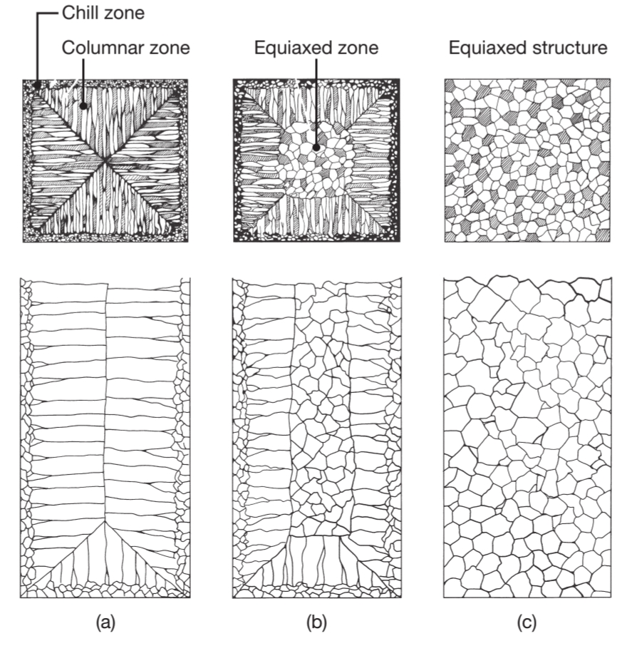
Schematic illustration of three cast structures of metals solidified in a square mold:
pure metals, with preferred texture at the cool mold wall. Note in the middle of the figure that only favorable oriented grains grow away the mold surface; solid-solution alloys; and structure obtained by heterogeneous nucleation of grains.
At the mold walls the metal cools rapidly (chill zone) because the walls are at ambient or slightly elevated temperature, and as a result, the casting develops a solidified skin (shell) of find equiaxed grains. The grains grow in the direction opposite to the heat transfer from the mold. Grains that have a favorable orientation, called columnar grains, grow preferentially.
Alloys
Because pure metals have limited mechanical properties, they are often enhanced and modified by alloying. The vast majority of metals used in engineering applications are some form of an alloy, defined as two or more chemical elements, at least one of which is a metal.
In Introduction to Material Engineering we have seen that solidification in alloys begins when the temprature drops below the liquidus,
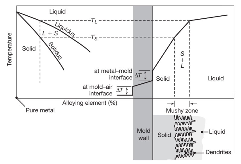
Schematic illustration of alloy solidification and temperature distribution in the solidifying metal. Note the formation of dendrites in the semi-solid (mushy) zone.
Note in the lower right of the figure the presence of liquid metal between the dendrite arms. Dendrites have three-dimensional arms and branches, which eventaully interlock, as shown in the next figure:
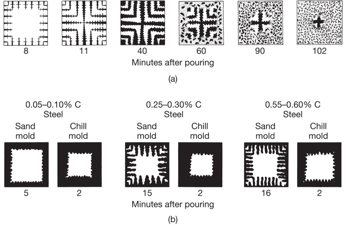
Solidification patterns for gray cast iron in a square casting. Note that after of cooling, dendrites reach other, but the casting is still mushy throught. It takes about two hours for this casting so solidify completely. Solidification of carbon steels in sand and chill (metal) molds. Note the difference in solidification patterns as the carbon content increases.
Slow cooling rate (on the order of
Structure-Property Relationships
Because all castings must possess certain specific properties to meet design and service requirements, the relationships between the properties and the structures developed during solidification are important considerations.
The compositions of dendrites and of the liquid metal in casting are given by the phase diagram of the particular alloy. Under normal cooling rates typically encountered in practice, cored dendrites are formed, which have a surface composition that is different from that at their centers. The surface has a higher concentration of alloying elements that at the core the dendrite, due to solute rejection from the core toward the surface during solidification of the dendrite (called microsegregation).
The darker shading in the interdendritic liquid near the dendrite shown in the following figure indicates that these regions have a higher solute concentration; consequently, microsegregation in these regions is much more pronounced than in others.
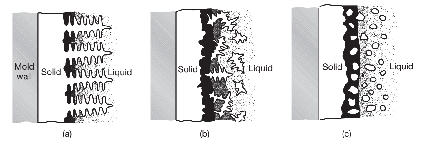
Schematic illustration of three basic types of cast structures: (a) columnar dendritic; (b) equiaxed dendritic; and (c) equiaxed nondendritic.
In contrast to microsegregation, macrosegregation involves differences in composition throughout the casting itself.
Heat Transfer
A major consideration in casting is the heat transfer during the complete cycle from pouring to solidification cooling of casting to room temperature. Heat flow at different location in the system depends on many factors, relating to the casting material and the mold and process parameters. For instance, in casting thin section, the metal flow rates must be high enough to avoid premature chilling and solidification. On the other hand, the flow rate must not be so high as to cause excessive turbulence.
Solidification Time
During the early states of solidification, a thin solidified skin begin to form at the cool mold walls; as time passes, the skin thickens. With flat mold walls, the thickness is proportional to the square root of time. Thus, doubling the time will make the skin
The solidification time is a function of the volume of a casting and its surface are (called Chvorinov’s rule), and is given by:
Where
The effects of mold geometry and elapsed time on skin thickness and its shape are shown in the following figure:
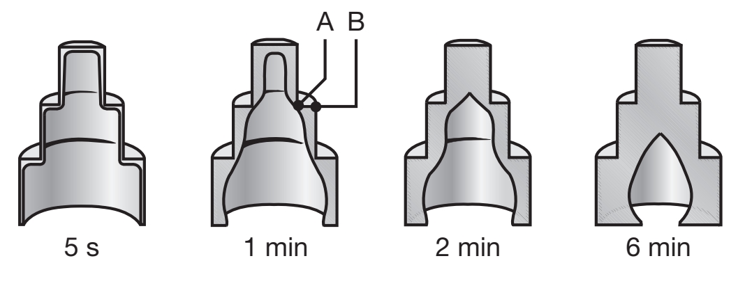
Solidified skin on a steel casting; the remaining molten metal is poured out at the times indicated in the figure. Hollow ornamental and decorative objects are made by a process called slush casting, which is based on this principle.
The unsolidified molten metal has been poured from the mold at different time intervals, ranging from
Note that the skin thickness increases with elapsed time, and that the skin is thinner at the external angles. Note that this operation is very similar to making hollow chocolate candies in various shapes.
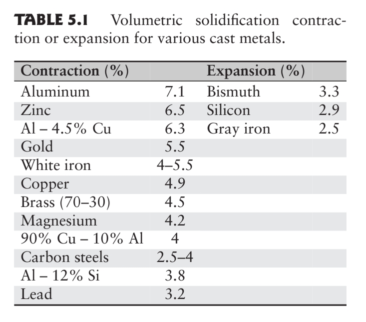
Shrinkage
Metals generally shrink during solidification and cooling to room temperature:
Shrinkage in a casting causes dimensional changes and sometimes cracking and is a result of of the following phenomena:
- Contraction of the molten metal as it cools before it begins to solidify.
- Contraction of the metal during phase change from liquid to solid (latent heat of fusion).
- Contraction of the solidified metal (the casting) as its temperature drops to ambient temperature.
The largest potential amount of shrinkage occurs during the phase change of the material from liquid to solid; this can be reduced or eliminated through the use of risers or pressure-feeding of molten metal.
Note that some metals, such as gray cast iron, expand. The reason is that graphite has a relatively high specific volume, and when it precipitates as graphite flakes during solidification of the gray cast iron, it causes a net expansion of the metal.
Expendable-Mold, Permanent-Pattern Casting Processes
Casting processes are generally classified according to (a) mold materials; (b) molding processes; and (c) methods of feeding the mold with the molten metal. The two major categories are expendable-mold and permanent-mold casting. Expendable-mold processes are further categorized as permanent pattern and expendable pattern processes. Expendable molds typically are made of sand, plaster, ceramics, and similar materials, which generally are mixed with various binders or bonding agents.
Sand casting
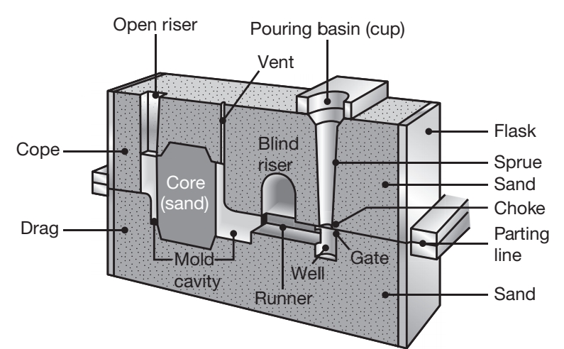
Cross section of a typical sand mold showing various features.
The sand casting process consists of (a) placing a pattern, having the shape of the desired casting, in sand to make an imprint; (b) incorporating a gating system; (c) filling the resuultin cavity with molten metal; (d) allowing the metal to solidify; (e) breaking away the sand mold; and (f) removing the casting and finishing it. Examples of parts made by sand casting are engine block, cylinder heads, machine-tool bases, and housings for pumps and motors.
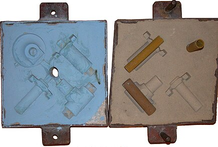
The cope and drag (top and bottom halves, respectively) of a sand mold, with cores in place on the drag.
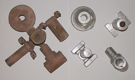
Two sets of castings (bronze and aluminum) from the above sand mold.
Shell-Mold Casting
Shell-mold casting has grown significantly because it can produce many types of castings with close dimensional tolerances, good surface finish, and at a low cost. In this process, a mounted pattern, made of a ferrous metal or aluminum, is heated to
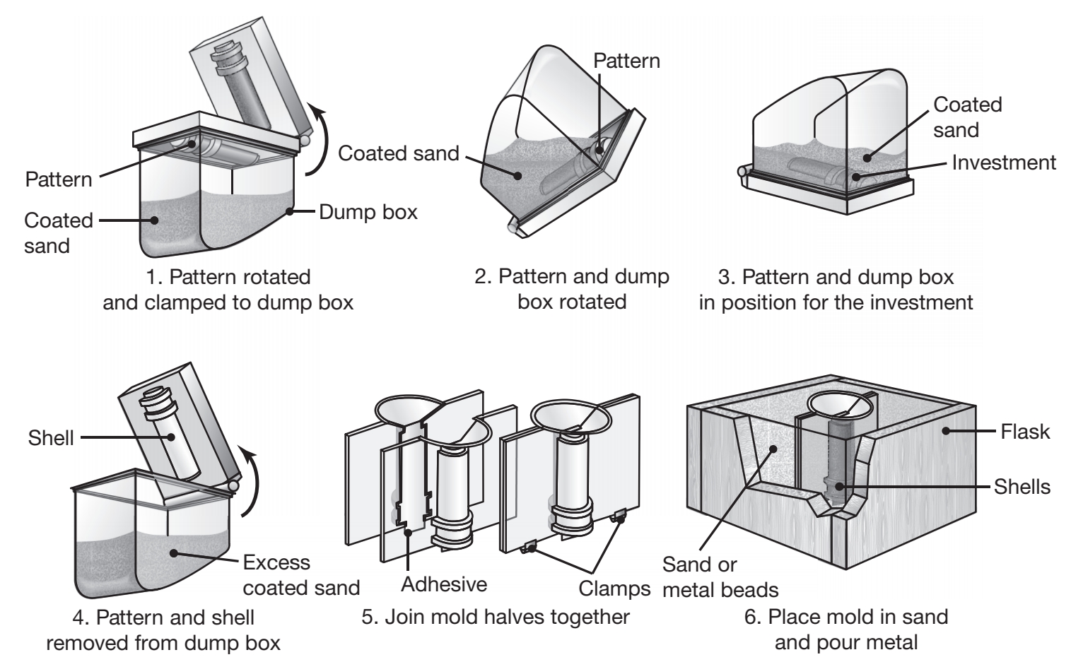
Schematic illustration of the shell-molding process, also called the dump-box technique.
The shells are light and thin, usually
Application include small mechanical parts requiring high precision, gear housings, cylinder heads, and connecting rods; the process is also widely used in producing high-precision molding cores, such as engine-block water jackets.
Expendable-Mold, Expendable-Pattern Casting Processes
Lost Foam Process
The expendable-pattern casting process uses a polystyrene pattern, which evaporates upon contact with the molten metal, to form a cavity for the casting.
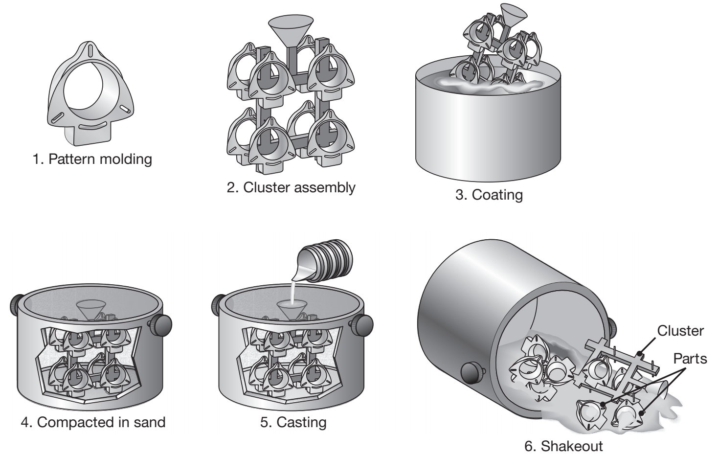
Schematic illustration of the expendable-pattern casting process, also known as lost-foam or evaporative-pattern casting.
Typical parts made are aluminum engine blocks, cylinder heads, crank-shafts, brake components, manifolds, and machine bases.
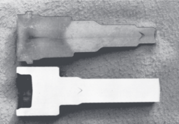
Lost Wax Process
In the lost was process, typical parts made are mechanical components such as gears, cams, valves, and ratchets; The pattern is made by injecting semisolid or liquid wax or plastic into a metal die in the shape of the pattern, or is made through ad dive manufacturing methods. The pattern is then removed and dipped into a slurry of refractory material. After this initial coating has dried, the pattern is coated repeatedly to increase its thickness. The one-piece mold is dried in air and heated to a temperature of
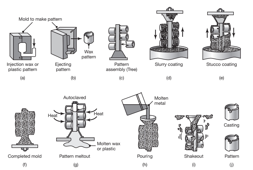
Schematic illustration of investment casting (lost wax process).
Permanent-Mold Casting Processes
Permanent molds are used repeatedly and are designed so that the casting can be easily removed and the mold reused. The molds are made of metals that maintain their strength at high temperatures. Because metal molds are better heat conductors than expendable molds, described above, the solidifying casting is subjected to a higher rate of cooling. This, in turn, affects the microstructure and grain size within the casting.
Permanent mold casting.
Low-Pressure Permanent Casting
Low-Pressure permanent mold (LPPM) casting uses a gas at low pressure (
The pressure is applied to the top of the pool of liquid, which forces the molten metal up a refectory pouring tube and finally into the bottom of the mold.
Die Casting (High-Pressure Casting)
Die casting is a metal casting process that is characterized by forcing molten metal under high pressure into the die cavity at pressures ranging from
Bulk Deformation Processes
From (Kalpakjian & Schmid, 2016):
In this chapter we will go over metalworking processes where the workpiece is subjected to plastic deformation, under forces applied through dies and tooling. Deformation processes generally are classified by type of operation as either primary working or secondary working; they are further divided into three categories of cold (room temperature), warm, and hot working.
Primary-working operation involve taking a solid piece of metal (generally from a cast state) and breaking it down successively into wrought material of various shapes by the basic processes of forging, rolling, extrusion, and drawing.
Secondary-working operation typically involve further processing of the products from primary working into final or semifinal products, such as bolts, gears, and sheet metal parts.
Forging
Forging denotes a family of processes used to make discrete parts, in which plastic deformation is caused by compressive stresses applied through various dies and tooling. Forging is one of the oldest metalworking operations, dating back to 5000 B.C.
Open-Die Forging
Open-die forging typically involves hot working and large deformations using simple tools such as flat dies, rounded sections, punches, or saddles.
A common process, known as upsetting, involves placing a solid cylindrical workpiece (the blank) between two flat dies (platens) and reducing its height.
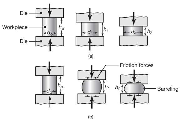
(a) Ideal deformation of a solid cylindrical specimen compressed between flat frictionless dies (platens), an operation known as upsetting. (b) Deformation in upsetting with friction at the die-workpiece interfaces. Note barreling of the billet caused by friction.
Because the volume of the cylinder remains constant in plastic deformation, any reduction in its height causes an increase in diameter. The reduction in height is defined as
where the subscript '
The engineering strain is
and the true strain
Barreling
In actual practice the specimen develops a barrel shape during upsetting, as shown in the following figure:
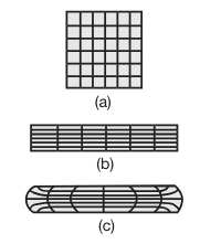
Schematic illustration of grid deformation in upsetting; (a) original grid pattern; (b) after deformation, without friction; and (c) after deformation, with friction. Such deformation patterns can be used to calculate the strains within a deforming body.
Barreling is caused primarily by frictional forces that oppose the radially outward flow of the material at the die-workpiece interfaces.
A result of barreling is that the deformation throughout the specimen becomes nonuniform or inhomogeneous
Forces under ideal conditions
If friction at the workpiece-die interfaces is zero and the material is perfectly plastic, with yield strength of
where
A typical true stress-true strain curve is shown in the following figure:
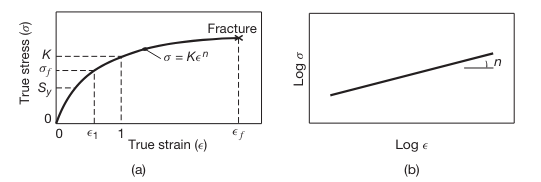
(a) True stress–true strain curve in tension. Note that, unlike in an engineering stress–strain curve, the slope is always positive and the slope decreases with increasing strain. Although in the elastic range stress and strain are proportional, the total curve can be approximated by the power expression shown. On this curve,
is the yield strength and is the flow stress. (b) True stress–true strain curve plotted on a log-log scale.
For convenience, such a curve is often approximated by the equation:
where the slope
If the material’s true stress-true strain curve is given by this equation, then the force at any stage during deformation becomes
where
For a work hardening material, the average flow stress is given by
We will sometimes assume the the material is rigid and perfectly plastic. For such material, once the stress reaches the yield strength
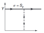
Schematic illustration of a rigid, perfectly plastic, idealized stress–strain curves.
Notes:
In the official course notes, there is no differentiation between
and , and denotes both of them with .
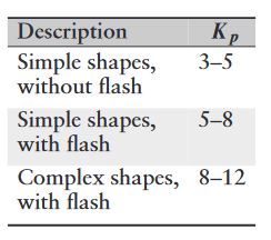
Slab Method of Analysis
There are several methods of analysis to theoretically determine stresses, strains, strain rates and forces in deformation processing. We will focus on the Slab method.
The slab method is one of the earlier and simpler methods of analyzing the stresses and loads in bulk-deformation processes. This method requires the selection of an element in the workpiece and identification of all the normal and frictional stresses acting on that element.
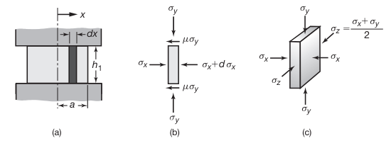
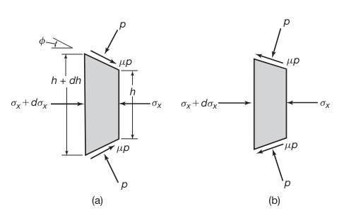
Stresses on an element in plane-strain compression (forging) between flat dies with friction. (Kalpakjian & Schmid, 2016).
After a lot of math, balancing forces, assuming
It can also be shown that the pressure
Where
Thus, the average pressure will be:
Distribution of die pressure, in dimensionless form of
, in plane-strain compression with sliding friction. Note that the pressure at the left and right boundaries is equal to the yield strength of the material in plane strain, .
For a disc-shaped cross section,
and the average pressure:
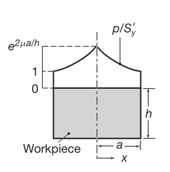
Impression-die forging
In impression-die forging, the workpiece acquires the shape of the die cavity (hence the term impression) while it is being deformed between the two closing dies.
Schematic illustrations of stages in impression-die forging. Note the formation of a flash, or excess material that subsequently has to be trimmed off.
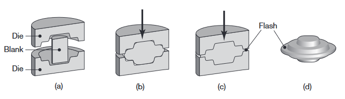
Forces in impression-die forging can be difficult to predict, because of the generally complex shapes involved and the fact that each location within the workpiece is typically subjected to different strains, strain rates, and temperatures, as well as variations in coefficient of friction along the die-workpiece contact area. Certain empirical pressure-multiplying factors,
where
Range of
values for impression-die forging.
Rolling
Rolling is the process of reducing the thickness or changing the cross section of a long workpiece by compressive forces applied through a set of rolls.
Rolling, which accounts for about
Rolling is first carried out at elevated temperatures (hot rolling), wherein the coarse-grained, brittle, and porous cast structure of the ingot or continuously cast metal is broken down into a wrought structure, with finer grain size and improved properties
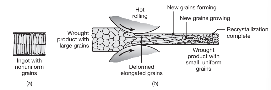
Changes in the grain structure of metals during hot rolling. This is an effective method to reduce grain size and refine the microstructure in metals, resulting in improved strength and good ductility.
Mechanics of Flat Rolling
The basic flat-rolling process is shown schematically in the following figure:
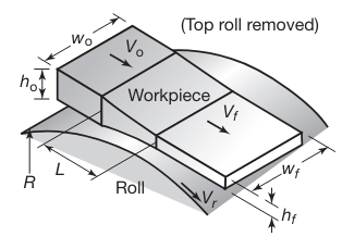
Schematic illustration of the flat-rolling process (Note that the top roll has been removed for clarity).
A strip of thickness
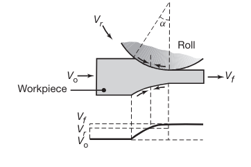
Relative velocity distribution between roll and strip surfaces. The arrows represent the frictional forces acting along the strip-roll interfaces. Note the difference in their direction in the left and right regions.
At one location along the arc of contact, however, the two velocities are the same; for this reason, this point is called the neutral point , neutral plane, or no-slip point. To the left of this point, the roll moves faster than the workpiece, and to the right, the workpiece moves faster than the roll.
Because of the relative motion at the interfaces, the frictional forces (which oppose motion) act on the strip surfaces in the directions shown in the last figure. In rolling, the frictional force on the left of the neutral point must be greater than the frictional force on the right. This difference results in a net frictional force to the right, making the rolling operation possible by pulling the strip into the roll gap.
Forward slip in rolling is defined as
and is a measure of the relative velocities at the exit of the work rolls.
Roll Pressure Distribution
It can be noted that the deformation zone in the roll gap is subjected to a state of stress similar to that in upsetting. However, the calculation of forces and stress distribution in rolling is more involved because the contact surfaces are curved. Also, in cold rolling, the material at the exit is strain hardened, and thus the flow stress at the exit is higher than that at the entry.
Stresses acting on an element in rolling: (a) entry zone and (b) exit zone.
It can be shown, that similar to upsetting, we can assume that
If we assume that the pressure distribution is symmetric, It can be shown that pressure distribution is given by (similar to Slab Method of Analysis in forging):
where
The average pressure distribution is given by:
If we don’t assume pressure distribution is symmetric, we get the following graph:
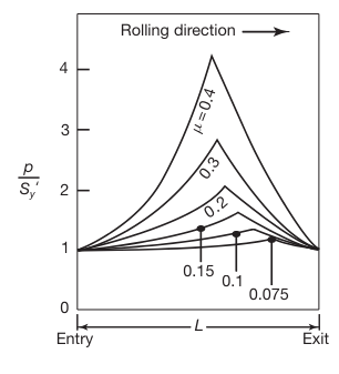
Pressure distribution in the roll gap as a function of the coefficient of friction. Note that as friction increases, the neutral point shifts toward the entry. Without friction, the rolls will slip, and the neutral point shifts completely to the exit.
Neutral Point Location
The neutral point (as explained in Rolling) is where the surface speed of the rolls matches the speed of the workpiece. The position of the neutral point depends on the balance of forward and backward friction forces. When friction increases, the force helping to move the workpiece through the rolls increases on the entry side. This enhanced frictional force shifts the neutral point toward the entry side because less force is needed to accelerate the workpiece to the roll speed.
Roll Forces
The roll force,
A simple method of calculating the roll force is to multiply the contact area by an average contact stress,
where
where
Roll Torque and Power
The roll torque,
The torque per roll is then
The power required per roll (usually there are 2 rolls, so just multiply by
where
Extrusion
In the extrusion process developed in the late 1700s for producing lead pipe, a billet is placed in a chamber and forced through a die opening by a ram. The die may be round or of various shapes. Typical parts made are railings for sliding doors, window frames, aluminum ladders, tubing, and structural and architectural shapes.
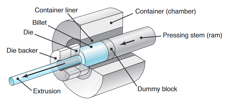
Schematic illustration of the direct-extrusion process. (Kalpakjian et al., 2014).
Two types of extrusions are direct and indirect extrusion:
- Direct extrusion (forward extrusion) is similar to forcing toothpaste through the opening of a tube. Note that the billet in this process moves relative to the container wall in the same direction as the extruded product.
- In indirect extrusion (reverse, inverted, or backward extrusion), the die moves toward the billet and there is no relative motion at the billet-container interface. Indirect extrusion is often used when the workpiece has a high level of friction with the billet, such as hot extrusion of steel.
Another important differentiation is between hot and cold extrusion processes:
- Hot extrusion: For metals and alloys that do not have sufficient ductility at room temperature, or in order to reduce the forces required, extrusion can be carried out at elevated temperatures.
- Cold extrusion: Developed in the 1940s, cold extrusion is a general term often denoting a combination of operations, such as a combination of direct and indirect extrusion and forging. The cold-extrusion process uses slugs cut from cold-finished or hot-rolled bars, wire, or plates.
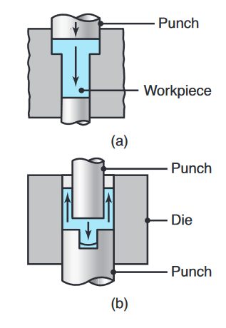
Two examples of cold extrusion; the arrows indicate the direction of metal flow during extrusion.
Mechanics of Extrusion
The force required for extrusion depends on (a) the strength of the billet material, (b) extrusion ratio, (c) friction between the billet, container, and die surfaces, and (d) process variables.
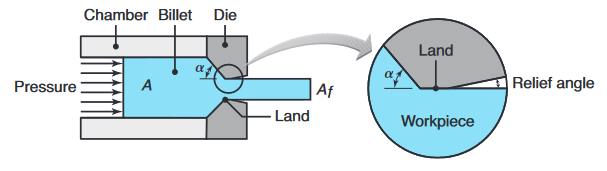
Process variables in direct extrusion; the die angle, reduction in cross-section, extrusion speed, billet temperature, and lubrication all affect the extrusion pressure. (Kalpakjian et al., 2014).
For a small die angle,
where
Extrusion Defects
Surface Cracking:
If extrusion temperature, friction, or speed is too high, surface temperatures can become excessive, which may cause surface cracking and tearing.
These cracks are intergranular (along the grain boundaries).
Surface cracking also may occur at lower temperatures, attributed to periodic sticking of the extruded part along the die land. Because of its similarity in appearance to the surface of a bamboo stem, it is known as a bamboo defect.
Internal Cracking:
The center of the extruded product can develop cracks, called center cracking, center-burst, arrowhead fracture, or chevron cracking:
Chevron cracking (central burst) in extruded round steel bars; unless the products are inspected, such internal defects may remain undetected and later cause failure of the part in service. (Kalpakjian et al., 2014).
Machining Processes
From (Kalpakjian & Schmid, 2016):
Machining processes are a critical component of manufacturing, used to shape and finish materials into precise and functional components. These processes involve removing material from a workpiece using various cutting tools and techniques to achieve desired dimensions, tolerances, and surface finishes. Machining is fundamental to the production of parts for a wide range of industries, including automotive, aerospace, electronics, and medical devices.
Turning
Turning is a fundamental machining process used in manufacturing to create cylindrical parts by removing material from a rotating workpiece using a cutting tool. This process is one of the most widely used and versatile methods in the manufacturing industry due to its ability to produce precise and intricate shapes with excellent surface finishes. Turning is typically performed on a lathe, which holds and rotates the workpiece against a single-point cutting tool that shapes the material.
Key Parameters and Equations
Examples of machining operations that can be performed on a lathe and similar machine tools.
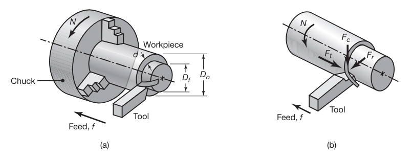
(a) Schematic illustration of a turning operation, showing depth of cut,
, and feed, . Cutting speed is the surface speed of the workpiece at the tool tip. (b) Forces acting on a cutting tool in turning. is the cutting force; is the thrust or feed force (in the direction of feed); and is the radial force that tends to push the tool away from the workpiece being machined. (Kalpakjian & Schmid, 2016).
-
Cutting Speed
where
-
Feed Rate
-
Depth of Cut
-
Cutting Time
If
-
Material Removal Rate (
Cutting Force and Power
The cutting force
where
The power
where
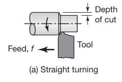
Straight Turning and Facing
Straight turning is a machining process performed on a lathe where a single-point cutting tool moves parallel to the axis of a rotating cylindrical workpiece. The primary purpose of straight turning is to reduce the diameter of the workpiece to achieve a desired dimension and surface finish.
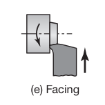
Facing is a machining process also performed on a lathe, where the cutting tool moves perpendicular to the axis of a rotating cylindrical workpiece. The goal of facing is to produce a flat surface at the end of the workpiece.
Surface Finish and Surface Integrity
Surface finish describes the geometric features of surfaces, whereas surface integrity pertains to properties that are strongly influenced by the type of surface produced.
Built-up edge and depth of cut can adversely affect surface finish and integrity. A shallow depth of cut (or dull tool) can also compromise surface finish. A dull cutting tool has a larger radius along its edges, just as a dull pencil or knife does.
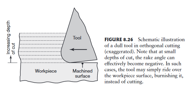
Schematic illustration of a dull tool in orthogonal cutting (exaggerated). Note that at small depths of cut, the rake angle can effectively become negative. In such cases, the tool may simply ride over the workpiece surface, burnishing it, instead of cutting. (Kalpakjian & Schmid, 2016).
If the radius is large in relation to the depth of cut, the tool will rub over the machined surface, generating frictional heat, inducing surface residual stresses, and causing surface damage, such as tearing and cracking.
In practice, the depth of cut should generally be greater than the radius on the cutting edge.
Feed marks:
In turning, as in some other machining operations, the cutting tool leaves a spiral profile (feed marks) on the machined surface as it moves across the workpiece.
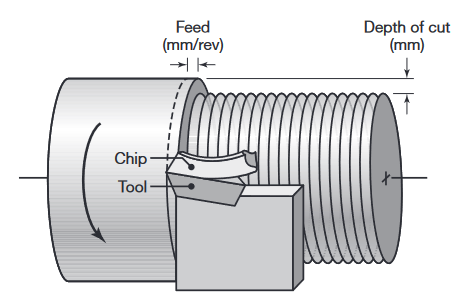
Terminology used in a turning operation on a lathe, where f is the feed (in mm/rev) and d is the depth of cut. (Kalpakjian & Schmid, 2016).
As expected, the higher the feed,
The total roughness height,
where
The Arithmetic Mean Roughness,
Milling
Milling is a machining process that involves the use of rotary cutters to remove material from a workpiece. The milling process can create a variety of features including flat surfaces, slots, and complex contours. The workpiece is usually held stationary while the cutting tool rotates and moves across the material to achieve the desired shape.
Types of milling operations:
- Face Milling: Produces flat surfaces by cutting with the end of the milling cutter.
- Peripheral Milling/Slab Milling: Involves cutting along the periphery of the cutter, used for creating deep slots, threads, and gear teeth.
- End Milling: Utilizes an end mill cutter to produce complex shapes, slots, and holes.
Key Parameters and Equations
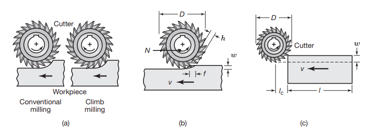
(a) Illustration showing the difference between conventional milling and climb milling. (b) Slab-milling operation, showing width of cut,
; feed per tooth, ; chip depth of cut, and workpiece speed, . (c) Schematic illustration of cutter travel distance, , to reach full depth of cut. (Kalpakjian & Schmid, 2016).
-
Cutting Speed
where
-
Feed Rate
where
-
Width of Cut
Note that the thickness of the chip in slab milling varies along its length, because of the relative longitudinal movement between the cutter and the workpiece.
-
Chip Thickness
-
Workpiece Speed
-
Cutting Time
Some other common parameters are related to the number of teeth in the milling cutter:
- Engagement angle
- Tooth pitch angle
- Number of teeth
- Number of effective teeth
$$
\boxed {
n=\dfrac{\alpha}{\beta}
} - Material Removal Rate (
Cutting Force and Power
The cutting force
or, its average for a whole width of cut
where
The power
where
Geometric Dimensioning and Tolerancing
סיבולות
- הסיבולת (Tolerance) של מידה פונקציונלית היא הסכום (תמיד תוספת ללא חיסור) של המידות המיוצרות שבהם הוא תלוי.
מדיד GO/NO GO
גל:
- עבור גל, מד No Go בודק את הגבול התחתון. אם החלק יכול להיכנס אז הוא קטן מהגבול התחתון.
- מד ה-Go בודק את הגבול העליון. אם החלק לא יכול להיכנס אז הוא גדול מהגבול העליון.
חור:
- עבור חור, מד No Go בודק את הגבול העליון. אם החלק יכול להיכנס אז החור גדול מהגבול העליון.
- מד ה-Go בודק את הגבול התחתון. אם החלק לא יכול להיכנס אז החור קטן מהגבול התחתון.
RSS
אם המידה הפונקציונלית
בהנחה ש-
Joining and Fastening Processes
From (Kalpakjian & Schmid, 2016):
Joining is a general, all-inclusive term covering numerous processes that are important in manufacturing. Joining may be preferred or necessary for one or more of the following reasons:
- The product is impossible or uneconomical to manufacture as a single piece;
- The product is easier and less costly to manufacture in individual components, which are then assembled;
- The product may have to be taken apart for repair or maintenance during its service life;
- Different properties may be required for function of the product; for example, surfaces that are subjected to friction and wear, or to corrosion and environmental attack, typically require characteristics different than those of the component’s bulk; and
- Transportation of the product in individual components and their subsequent assembly may be easier and more economical than transporting it as a single unit.
There are many categories of joining and fastening processes; In our course we will focus on welding and brazing and soldering.
| Topic | Subtopic | Details |
|---|---|---|
| Fusion Welding | Involves melting and coalescing materials by heat, typically using electrical or other means. | |
| Oxyfuel Gas Welding (OFW) | Developed in the early 1900s. Uses a fuel gas and oxygen to produce a flame for melting metals at the joint. | |
| Arc Welding Processes | Uses electrical energy to generate heat via an electric arc. Involves consumable or nonconsumable electrodes. | |
| Arc Welding Processes: Consumable Electrode | Shielded Metal Arc Welding (SMAW) | One of the oldest and most versatile processes. Generates an electric arc by touching and withdrawing a coated electrode. |
| Gas Metal Arc Welding (GMAW) | Shielded by an external gas source. Developed in the 1950s. Suitable for ferrous and nonferrous metals. Doubles welding productivity compared to SMAW. | |
| Arc Welding Processes: Nonconsumable Electrode | Gas Tungsten Arc Welding (GTAW) | Uses a nonconsumable tungsten electrode. Filler metal supplied from a filler wire. |
| Plasma Arc Welding (PAW) | Uses ionized hot gas (plasma) for welding. Greater energy concentration, better arc stability, less thermal distortion, and higher welding speeds compared to other arc welding processes. | |
| High Energy Beam Welding | Includes electron-beam welding (EBW) and laser-beam welding (LBW), which offer high quality and technical advantages in modern manufacturing. | |
| Electron-Beam Welding (EBW) | Heat generated by high-velocity, narrow-beam electrons, converting kinetic energy to heat upon striking the workpiece. | |
| Laser-Beam Welding (LBW) | Uses a high-power laser for heat, with deep penetrating capability suitable for deep and narrow joints. | |
| Oxyfuel–gas Cutting (OFC) | Similar to oxyfuel gas welding but used to remove a narrow zone from metal plates or sheets. | |
| Resistance Welding (RW) | Heat generated by electrical resistance between two joined members. | |
| Brazing and Soldering | Lower temperatures compared to welding. Brazing involves melting a filler metal placed between surfaces to be joined. |
The Fusion Welded Joint
Fusion welding is a process where the workpieces are joined by melting their edges together and adding filler material if necessary. This chapter focuses on the characteristics, advantages, and limitations of fusion welded joints.
Key Points:
- Strength and Defects: Fusion welded joints can be as strong as the base materials, but they are susceptible to defects like porosity, cracking, and residual stresses.
- Thermal Effects: The heat from welding can lead to significant thermal distortion and residual stresses, which may weaken the joint.
- Metallurgical Considerations: The microstructure of the weld metal and the heat-affected zone (HAZ) plays a crucial role in determining the mechanical properties of the joint. Careful control of cooling rates and heat input is necessary to avoid undesirable phases and grain growth.
A typical fusion welded joint is shown in the following figure:
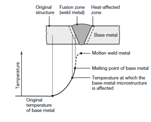
Characteristics of a typical fusion weld zone in oxyfuel gas welding and arc welding processes (Kalpakjian & Schmid, 2016).
Three distinct zones are identified:
- The base metal, the metal to be joined;
- The heat-affected zone (HAZ); and
- The fusion zone, the region that melts during welding.
After heat has been applied and the filler metal (if any) has been introduced into the weld zone, the molten weld begins to solidify and cool. The solidification process is similar to that in casting and begins with the formation of columnar (dendritic) grains; These grains are relatively long and form parallel to heat flow. Because metals are much better heat conductors than the surrounding air, the grains lie parallel to the plane of the two plates or sheets being welded.
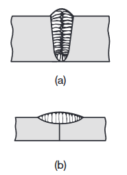
Grain structure in (a) a deep weld and (b) a shallow weld. Note that the grains in the solidified weld metal are perpendicular to their interface with the base metal.
The grains developed in a shallow weld are shown in the figure above (b).
The weld metal has a cast structure, and because it has cooled rather slowly, it typically has coarse grains; consequently, the metal has relatively low strength, hardness, toughness, and ductility. These properties can, however, be improved with proper selection of filler metal composition and with subsequent heat treatment of the joint.
Weld Quality
Because of its past history of thermal cycling and the attendant microstructural changes, a welded joint may develop discontinuities that can be caused by inadequate or careless application of established welding procedures or poor operator training. The major discontinuities that affect weld quality are described below:
-
Porosity in welds may be caused by (a) trapped gases that are released during melting of the weld zone but trapped during solidification of the weld zone; (b) chemical reactions that occur during welding; or (c) contaminants present in the weld zone.
-
Slag inclusions. These inclusions may be trapped in the weld zone. If the shielding gases used are not effective, contamination from the environment may contribute to slag inclusions.
-
Incomplete fusion and incomplete penetration. Incomplete fusion (lack of fusion) produces poor weld beads, such as those shown in the following figure:
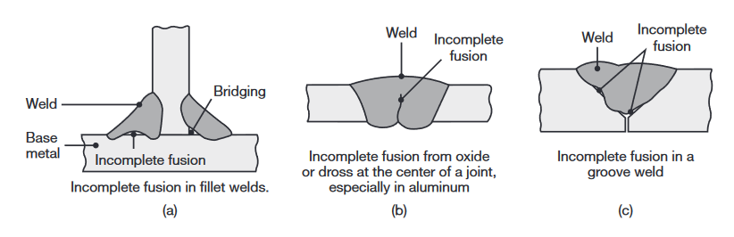
Examples of various incomplete fusion in welds.
-
Weld profile. Weld profile is important not only because of its effects on the strength and appearance of the weld but also because it can indicate incomplete fusion or the presence of slag inclusions in multiplayer welds.
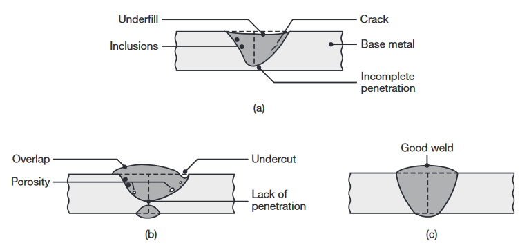
Examples of various defects in fusion welds.
-
Cracks. Cracks may develop at various locations and directions in the weld zone. Cracks generally result from a combination of the following factors:
- Temperature gradients, causing thermal stresses in the weld zone;
- Variations in the composition of the weld zone, causing different contractions;
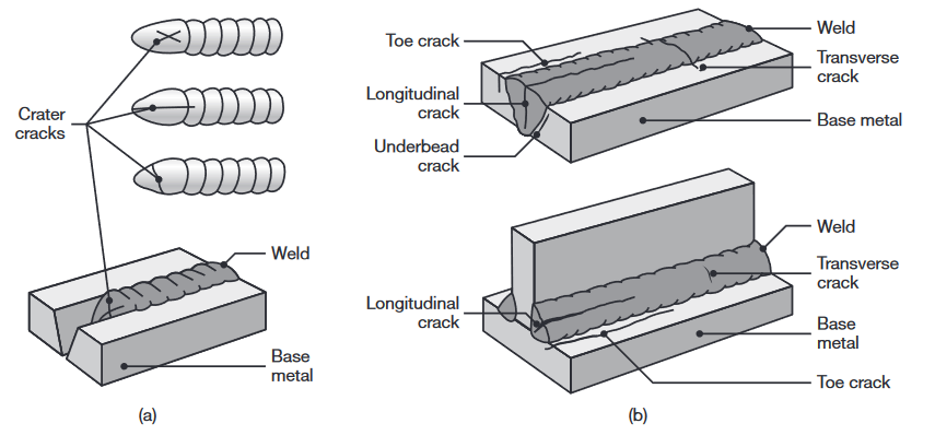
Types of cracks in welded joints. The cracks are caused by thermal stresses that develop during solidification and contraction of the weld bead and the welded structure.
Cracks are classified as hot cracks, developing while the joint is still at elevated temperatures, and cold cracks, that develop after the weld metal has solidified.
6. Residual stresses. Because of localized heating and cooling during welding, expansion and contraction of the weld area develop residual stresses.
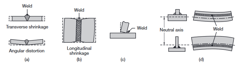
>Distortion and warping of parts after welding, caused by differential thermal expansion and contraction of different regions of the welded assembly. Warping can be reduced or eliminated by proper weld design and fixturing prior to welding.
Heat Treating Ferrous Alloys
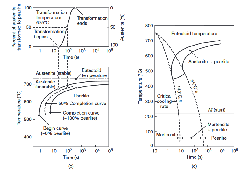
(a) Austenite to pearlite transformation of iron-carbon alloys as a function of time and temperature. (b) Isothermal transformation diagram obtained from (a) for a transformation temperature of
. (c) Microstructures obtained for a eutectoid iron-carbon alloy as a function of cooling rate.
Tempered martensite:
Tempering is a heating process that reduces martensite’s hardness and improves its toughness. The body-centered tetragonal martensite is heated to an intermediate temperature, where it transforms to a two-phase microstructure, consisting of body-centered cubic alpha ferrite and small particles of cementite. Longer tempering time and higher temperature decrease martensite’s hardness. The reason is that the cementite particles coalesce and grow, and the distance between the particles in the soft ferrite matrix increases as the less stable, smaller carbide particles dissolve.
Austenitization:
Austenitization means to heat the iron, iron-based metal, or steel to a temperature at which it changes crystal structure from ferrite to austenite.
Quenching:
Quenching may be carried out in water, brine (saltwater), oils, molten salts, or air, as well as caustic solutions, polymer solutions, and various gases. Because of the differences in the thermal conductivity, specific heat, and heat of vaporization of these media, the rate of cooling also will be different.
Heat Treating Nonferrous Alloys and Stainless Steels
Nonferrous alloys and some stainless steels generally cannot be heat treated by the techniques for ferrous alloys, because nonferrous alloys do not undergo phase transformations as steels do. Heat-treatable aluminum alloys, copper alloys, and martensitic and precipitation-hardening stainless steels are hardened and strengthened by precipitation hardening. This is a technique in which small particles of a different phase (called precipitates) are uniformly dispersed in the matrix of the original phase. Precipitates form because the solid solubility of one element (one component of the alloy) in the other is exceeded.
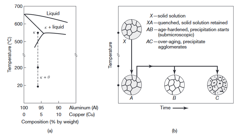
(a) Phase diagram for the aluminum-copper alloy system. (b) Various microstructures obtained during the age-hardening process (Kalpakjian & Schmid, 2016).
Solution treatment:
In solution treatment the alloy is heated to within the solid-solution
Precipitation hardening:
The structure obtained in
Aging:
Because the precipitation process is one of time and temperature, it is also called aging, and the property improvement is known as age hardening. If carried out above room temperature, the process is called artificial aging. Several aluminum alloys harden and become stronger over a period of time at room temperature, by a process known as natural aging.
These alloys are first quenched and then, if required, are formed at room temperature into various shapes, and allowed to develop strength and hardness by natural aging. Natural aging can be slowed by refrigerating the quenched alloy.
In the precipitation process, as the reheated alloy is held at that temperature for an extended period of time, the precipitates begin to coalesce and grow. They become larger but fewer, as shown by the larger dots in
Surface Treatments, Coatings, and Cleaning
From (Kalpakjian & Schmid, 2016):
After a part or a component is manufactured, all or specific areas of its surfaces may have to be further processed in order to impart certain specific properties and characteristics. Surface treatments may be necessary to:
- Improve surface roughness, appearance, dimensional accuracy, and frictional characteristics;
- Improve resistance to wear, erosion, and indentation (such as the slideways in machine tools; surfaces susceptible to wear; and shafts, rolls, cams, gears, and bearings);
- Control friction in contacting surfaces of tools, dies, bearings, and machine ways;
- Improve resistance to corrosion and oxidation, which is of particular concern with sheet metals for automotive or other outdoor uses, gasturbine components, and medical devices;
- Improve fatigue resistance, as with bearings and shafts; and
- Impart decorative features, color, or special surface texture.
Surface Treatment Processes
Several processes are used for surface treatments, based on mechanical, chemical, thermal, and physical methods.
| Process | Description |
|---|---|
| Shot peening, water-jet peening, and laser shot peening | The surface of the workpiece is impacted repeatedly with cast-steel, glass, or ceramic shot (small balls). they make overlapping indentations on the surface, inducing plastic deformation of the surface, to depths up to The process imparts compressive residual stresses on the surface, thus improving the fatigue life of the component. |
| Roller burnishing (surface rolling) | The component surface is cold worked using a hard and highly polished roller or a series of rollers |
| Thermal spraying (metallizing) | Metal in the form of rod, wire, or powder is melted in a stream of oxyacetylene flame, electric arc, or plasma arc, and the droplets are sprayed onto a preheated surface at speeds up to The surfaces to be sprayed may be roughened to improve bond strength. Bond strength of Combustion spraying – oxyfuel flame or detonation gun (controlled and repeated explosions), medium strength. In Electrical spraying – arc or plasma, yields good strength. In cold spraying – the particles to be sprayed are not melted, minimal oxidation |
| Vapor deposition | The workpiece is surrounded by chemically reactive gases that contain chemical compounds of the materials to be deposited. The coating thickness is a few In physical vapor deposition (PVD), the process is carried out in high vacuum and temperatures in the range of In chemical vapor deposition (CVD) the tools are placed on a graphite tray and are heated to Heating – 3 hours, coating – 4 hours, cooling – 6-8 hours. |
| Electroplating | The workpiece (cathode) is plated with a different metal (anode) while both are suspended in a bath containing a waterbase electrolyte solution. |
| Electroless plating | The process is carried out by chemical reaction without the use of external source of electricity. The coating has excellent wear and corrosion resistance, and has a uniform thickness. |
| Hot dipping | The workpiece (usually steel or iron) is dipped into a bath of molten metal, such as zinc, tin, aluminum (aluminizing), and terne. Hot-dipped coatings on discrete parts or sheet metal provide galvanized pipe, plumbing supplies, and numerous other products with long-term resistance to corrosion. |
| Anodizing | Anodizing is an oxidation process whereby the workpiece surfaces are converted to a hard and porous oxide layer that provides corrosion resistance and a decorative finish. |
| Diffusion coating | In this process, an alloying element is diffused into the surface, thus altering its properties; the elements can be in solid, liquid, or gaseous states. |
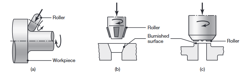
Examples of roller burnishing of (a) the fillet of a stepped shaft, (b) an internal conical surface, and (c) a flat surface (Kalpakjian & Schmid, 2016).
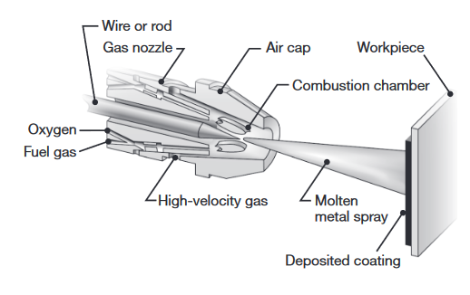
Schematic illustration of thermal wire spraying (Kalpakjian & Schmid, 2016).
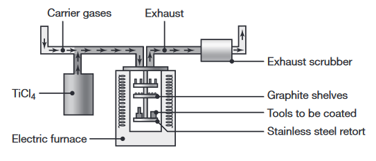
Schematic illustration of the chemical vapor deposition process (Kalpakjian & Schmid, 2016).
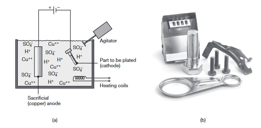
(a) Schematic illustration of the electroplating process. (b) Examples of electroplated parts. (Shutterstock/Osipov Petr) (Kalpakjian & Schmid, 2016).
Powder Metallurgy and Processing of Ceramics and Glasses
Powder Metallurgy
Production of Metal Powders
Metal powders can be produced by several methods, the choice of which depends on the particular requirements of the end product. Sources for metals generally are their bulk form, ores, salts, and other compounds. These forms are then produced, by various methods, into powders.
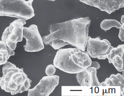
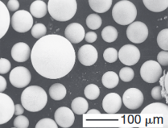
(top) Scanning-electron microscope image of iron powder particles made by atomization. (bottom) Nickelbased superalloy (Udimet 700) powder particles made by the rotating electrode process; Source: P.G Nash.
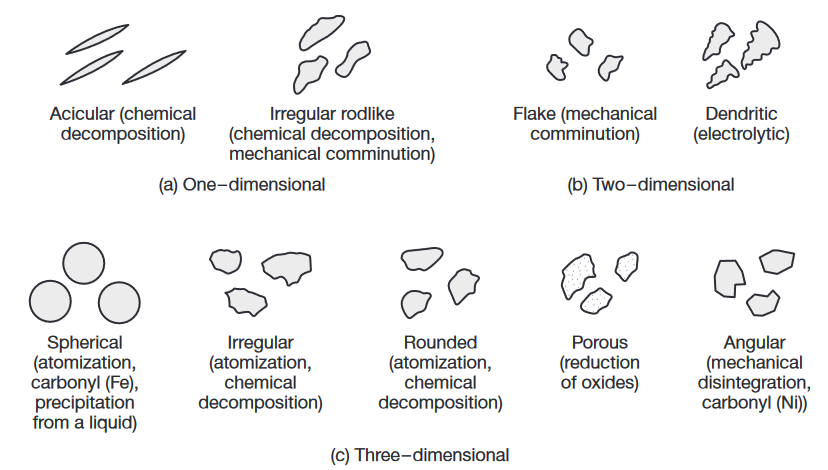
Particle shapes and characteristics of metal powders and the processes by which they are produced. (Kalpakjian & Schmid, 2016).
Compaction of Metal Powders
Compaction is the step in which the blended powders are pressed into specific shapes using dies and presses that are either hydraulically or mechanically actuated.
The purposes of compaction are to obtain the required shape, density, and particle-to-particle contact, and to make the part sufficiently strong to be handled and processed further.
Density is relevant during three different stages in PM processing: (a) as loose powder; (b) as a green compact; and (c) after sintering.
Porosity
The particle shape, average size, and size distribution all affect the packing density of loose powder. An important factor in density is the size distribution of the particles. If all of the particles are of the same size, there will always be some porosity when packed together. Theoretically, the porosity is at least
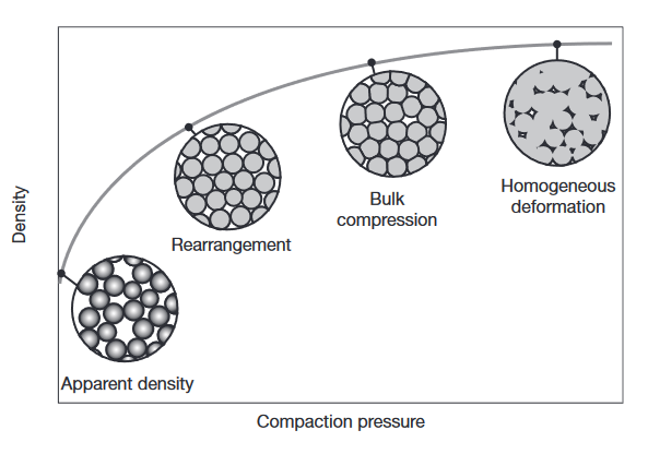
Compaction of metal powders: at low pressures, the powder rearranges without deforming, leading to a high rate of density increase. Once the powders are more closely packed, plastic deformation occurs at their interfaces, leading to further density increases but at lower rates. At very high densities, the powder behaves like a bulk solid.
Isostatic Pressing
For improved compaction, PM parts may be subjected to a number of additional operations, such as rolling, forging, and isostatic pressing. Because the density of die-compacted powders can vary significantly, powders can be subjected to hydrostatic pressure in order to achieve more uniform compaction.
In cold isostatic pressing (CIP), the assembly is pressurized hydrostatically in a chamber, usually filled with water. The most common pressure is
In hot isostatic pressing (HIP), the container is usually made of a high melting-point sheet metal. typical operating condition for HIP is
In Pressure-less compaction, the die is filled with metal powder by gravity, and the powder is sintered directly in the die. Because of the resulting low density, pressure-less compaction is used principally for porous parts, such as filters.
Sintering
Sintering is the process whereby compressed metal powder is heated in a controlled-atmosphere furnace to a temperature below its melting point, but sufficiently high to allow bonding (fusion) of the individual metal particles.
Sintering mechanisms
Sintering mechanisms are complex and depend on the composition of the metal particles as well as the processing parameters. As the temperature increases, two adjacent particles begin to form or strengthen a bond by diffusion (solid-state bonding), as shown in the following figure:
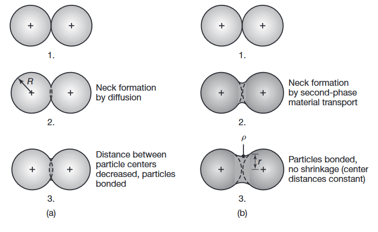
Schematic illustration of two basic mechanisms in sintering metal powders: (a) solid-state material transport and (b) liquid-phase material transport.
is the particle radius, is the neck radius, and is the neck profile radius.
As a result, the strength, density, ductility, and thermal and electrical conductivities of the compact increase. At the same time, however, the compact shrinks, hence allowances should be made for shrinkage, as is done in casting.
Ceramics: Structure, Properties, and Applications
Ceramics are compounds of metallic and nonmetallic elements. The term ceramics refers both to the material and to the ceramic product itself.
Some properties of ceramics are significantly better than those of metals, particularly their hardness and thermal and electrical resistance. Ceramics are available as single crystal or in polycrystalline form.
Grain size has a major influence on the properties of ceramics; the finer the size, the higher is the strength and the toughness (fine ceramics).
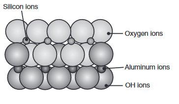
The crystal structure of kaolinite, commonly known as clay. (Kalpakjian & Schmid, 2016).
General Properties and Applications of Ceramics
Compared with metals, ceramics have the following general characteristics: brittleness, high strength and hardness at elevated temperatures, high elastic modulus, low toughness, low density, low thermal expansion, and low thermal and electrical conductivity. However, because of the wide variety of compositions and grain size, the mechanical and physical properties of ceramics can vary significantly.
Because of their sensitivity to cracks, impurities, and porosity, ceramics’ strength in tension is approximately one order of magnitude lower than their compressive strength. Such defects lead to the initiation and propagation of cracks, under tensile stresses, severely reducing tensile strength.
Tensile strength:
The tensile strength of polycrystalline ceramic parts increases with decreasing grain size and increasing porosity. Common earthenware, for example, has a porosity of
where
Modulus of elasticity:
The modulus of elasticity of polycrystalline ceramic is affected by porosity, as given by:
where
Thermal conductivity
Ceramics’ thermal conductivity varies by as much as three orders of magnitude, depending on composition, whereas the thermal conductivity of metals varies by one order of magnitude. Also, as with other materials, thermal conductivity decreases with increasing temperature and porosity (because air is a very poor thermal conductor).
The thermal conductivity, k, is related to porosity by
where
Additive Manufacturing
Stereolithography
The stereolithography (STL) or vat photopolymerization process is based on the principle of curing (hardening) a liquid photopolymer into a specific shape. Consider what happens when a laser beam is focused on and translated across the surface of a liquid photopolymer. The laser serves to cure the photopolymer by providing the energy necessary for polymerization.
Powder Bed Processes
Powder bed processes involve a number of processes that utilize powder as the workpiece material, and where the powder is deposited layer-by-layer in a bed or build chamber or cylinder.
Selective laser melting (SLM):
is a process based on selectively sintering of polymeric or metallic powders into an individual object.
In this process, a thin layer of powder is first deposited in the part-build cylinder. A laser beam, guided by a computer (using instructions generated by the 3D CAD program of the desired part), is then focused on that layer, tracing and melting a particular cross section, which then rapidly resolidifies into a solid mass (after the laser beam is moved to another section). The powder in other areas remains loose, but supports the solid portion. Another layer of powder is then deposited, and this cycle is repeated until the entire three-dimensional part has been produced.
Electron beam melting (EBM):
A process similar to selective laser sintering and electron-beam welding, electron-beam melting uses the energy source associated with an electron beam to melt metal powder (such as titanium, stainless steel, or cobalt-chrome) to make metal prototypes.
Diffusion in Powder Bed Processes
The diffusion processes in Electron Beam Melting (EBM) and Selective Laser Melting (SLM) can be described using equations from thermodynamics and materials science. We will focus on Arrhenius Equation:
Theorem:
The diffusion coefficient
is temperature-dependent and follows the Arrhenius relationship: where
is called the pre-exponential factor (related to the material); is the activation energy for diffusion (also related to the material); is the universal gas constant; and is the absolute temperature (in Kelvin).
This equation shows that diffusion rates increase exponentially with temperature, which is particularly relevant in high-temperature processes like EBM and SLM.
Another important concept is called the characteristic length of diffusion. it is Used to estimate the distance over which diffusion occurs within a certain period of time. It provides insight into how far particles, atoms, or molecules can move through a medium due to diffusion over a given timescale.
Definition:
The characteristic length
of diffusion is typically defined as the distance over which a diffusing species spreads in a material over a certain time . It is derived from the solution to Fick’s Second Law of Diffusion for certain boundary conditions. For a simple diffusion process in one dimension, the characteristic length can be estimated using the following relationship: where
is the Diffusion coefficient (rate of diffusion); and is the time over which diffusion occurs.
Energy Balance Equation for Powder Bed Processes
The energy balance equation is essential in understanding the thermal processes during Electron Beam Melting (EBM) in an ARCAM machine. This equation ensures that the energy supplied by the electron beam is correctly accounted for, influencing the melting, solidification, and cooling phases of the process.
The general form of the energy balance equation in an EBM system can be described as:
-
where
-
where
-
where
Sometimes we also pass the boiling point of the material. In that case, we need to use two different specific heat capacities;where