from (Lynch & Park, 2017):
Forward Kinematics
The forward kinematics of a robot refers to the calculation of the position and orientation of its end-effector frame from its joint coordinates
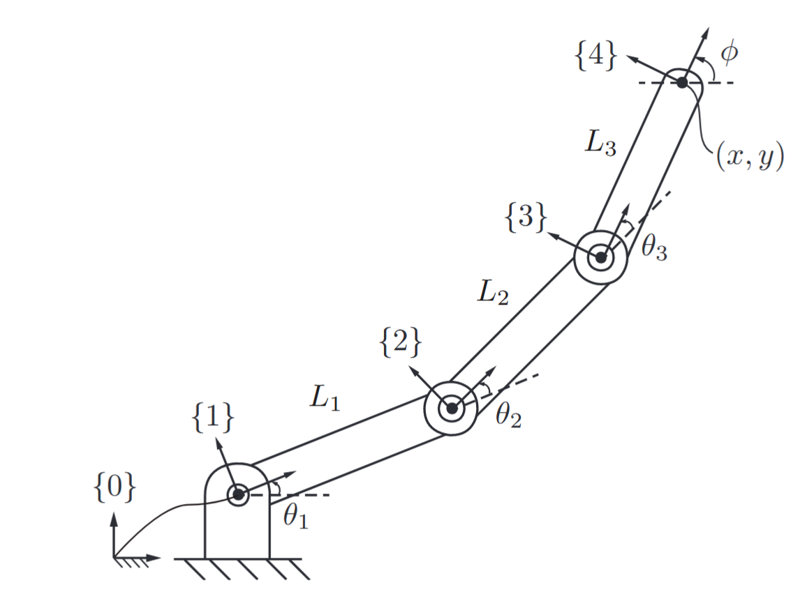
Forward kinematics of a
planar open chain. For each frame, the and is shown; the -axes are parallel and out of the page. (Lynch & Park, 2017).
The link lengths are
A more systematic method of deriving the forward kinematics might involve attaching reference frames to each link
where
Assigning Link Frames
One widely used representation for the forward kinematics of open chains relies on the Denavit–Hartenberg parameters (D–H parameters), and this representation uses equation (LP4.4).
The basic idea underlying the Denavit–Hartenberg approach to forward kinematics is to attach reference frames to each link of the open chain and then to derive the forward kinematics from the knowledge of the relative displacements between adjacent link frames.
Rather than attaching reference frames to each link in an arbitrary fashion, in the Denavit–Hartenberg convention a set of rules for assigning link frames is observed. The following figure illustrates the frame assignment convention for two adjacent revolute joints
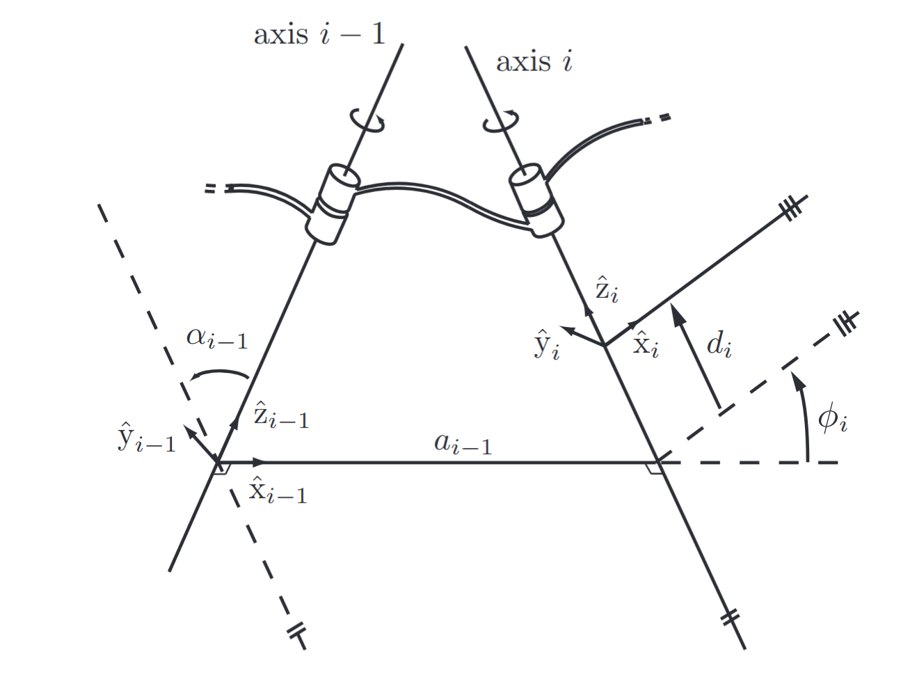
Illustration of the Denavit–Hartenberg parameters. (Lynch & Park, 2017).
The first principle in assigning reference frames is that the
Once the direction of the
The origin of frame
With the origin defined, the remaining axes of the frame follow naturally:
- The
- The
The figure above shows the resulting frames
With the frames defined, we now introduce four parameters that fully describe the transformation
- Link twist
- Link length
Note:
Despite the name, this does not necessarily represent the actual physical length of the link.
- Link offset
: The distance from to along - Joint angle
: The angle from to , measured around the -axis.
These four parameters are known collectively as the Denavit–Hartenberg parameters. For an open-chain robotic arm with
If all joints are revolute:
- The parameters
- The joint angle
We will now address:
- Cases where the perpendicular line is undefined or not unique.
- Scenarios with prismatic joints.
- Guidelines for selecting the ground and end-effector frames.
When Adjacent Revolute Joint Axes Intersect
If two consecutive revolute joint axes intersect, then no single line exists that is perpendicular to both axes. In such situations, we assign the link length
This setup yields two valid options: one that results in a positive link twist angle
When Adjacent Revolute Joint Axes Are Parallel
Another special case arises when two adjacent revolute joint axes are parallel. Here, infinitely many perpendicular lines can be drawn between the axes (technically, a one-dimensional family of such lines exists), and any of them can be used to define the frame.
The general recommendation is to pick the perpendicular line that feels most physically meaningful and simplifies the D–H parameters—ideally resulting in more zeros.
Prismatic Joints
For prismatic joints, the
Under this convention:
- The link offset
- The joint angle
The method for setting the origin and determining the
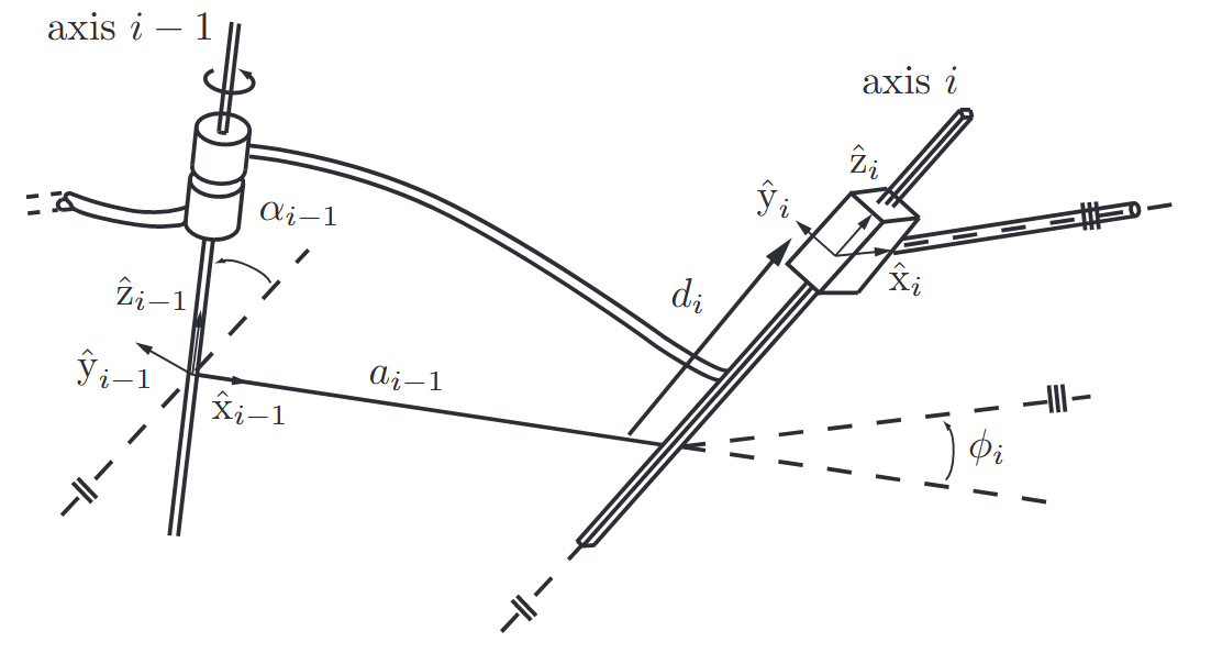
Link frame assignment convention for prismatic joints. Joint
is a revolute joint, while joint is a prismatic joint. (Lynch & Park, 2017).
Choosing the Ground and End-Effector Frames
So far, we’ve discussed how to assign link frames, but not how to define the ground (base) frame or the final end-effector frame. A helpful strategy is to choose these in a way that feels intuitive and results in the simplest possible D–H parameter set.
Typically:
- The ground frame is placed to coincide with frame
- For a revolute joint, this leads to
- For a prismatic joint, we get
- The end-effector frame is positioned at a convenient reference point on the tool or device, chosen for clarity in task description and simplification of D–H parameters (ideally making them zero where possible).
Keep in mind, though, that not all arbitrary frame choices will work—there may be no valid set of D–H parameters that describe the transformation if the initial or final frames are chosen inconsistently. This point will be addressed in further detail.
Manipulator Forward Kinematics
Once all the transformations
Exercises
Note:
Question 1
Given the robot shown in the figure below:

Simple robot with one revolute and one prismatic joint.
Compute the last transformation
Solution:
First, let’s assign link frames.

Assigning link frames.
We need to establish our coordinate frames according to the D–H parameters.
We will compute each transformation matrix using the D–H parameters from the table.
For each joint, the transformation matrix is:
Computing each individual transformation matrix:
Therefore the last transformation:
Question 2
Compute the forward kinematics of the following manipulator:

A manipulator with 2 revolute and 1 prismatic joints.
Solution:
First, we’ll mark the

Marking
axes along the joints’ axes.
Now we can complete the other frames, starting from the world frame:

Assigning all the frames according to the convention.
Now to plot all the parameters in a table:
The forward kinematics will then be: