Experimental Validation of Electromechanical Buckling
Electromechanical buckling (EMB) is a bifurcation instability in which an elastic structure is destabilized by the combined action of axial loading and a symmetric electrostatic field. The key idea is that two different bifurcation mechanisms, mechanical buckling and electrostatic bifurcation, can be described by one critical stability curve. (Abu-Salih & Elata, 2006).
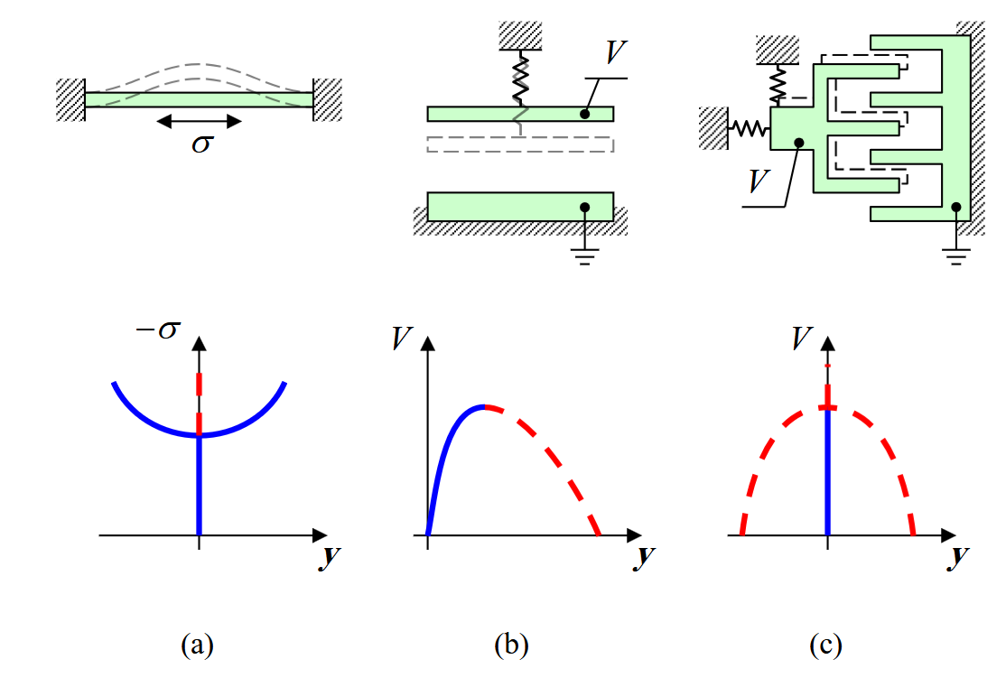
Figure 4.1: Instability responses: mechanical buckling of a compressed beam, pull-in of a parallel-plate actuator, and side pull-in of a comb-drive. (Abu-Salih & Elata, 2006).
Mechanical buckling occurs only when the compressive axial load exceeds a critical value. Pull-in of a usual parallel-plate actuator is different: it is a limit point, so the system loses stability in one prescribed direction. Electrostatic side pull-in, however, is a bifurcation, because the structure can collapse in either of two symmetric directions.
EMB combines these ideas. A slender beam is subjected to an axial load and to two equal side voltages. The symmetric electrostatic field does not choose an initial side. Instead, it reduces the stiffness of the symmetric equilibrium until the straight configuration loses stability.
Why this is not ordinary pull-in
In a one-sided parallel-plate actuator, the voltage force already points toward the fixed electrode. In the EMB structure, the two side electrodes are symmetric. The straight beam sees equal attraction on both sides, so it remains an equilibrium configuration until that equilibrium becomes unstable.
Symmetric Electrostatic Bifurcation
A simple lumped model that captures the electrostatic part of the phenomenon is a grounded movable plate suspended by a spring between two fixed electrodes held at the same voltage

Figure 4.2: Symmetric parallel-plate actuator used as a lumped model for electrostatic bifurcation.
Using the voltage-controlled potential convention from a previous lecture, the total potential is
Define
Then
The equilibrium equation is
One equilibrium is always
At
Below this voltage the plate remains centered. At the critical voltage, it can collapse toward either side. This is a bifurcation, not a one-sided fold.
Clamped-Guided EMB Model
The experimentally validated structure is a clamped-guided beam placed symmetrically between two fixed side electrodes. The guided end allows axial load to be prescribed externally.

Figure 4.3: Clamped-guided beam subjected to axial load
and a symmetric electrostatic field. One buckled configuration is shown by a dashed line. (Abu-Salih & Elata, 2006).
At the onset of buckling the deflection is small, so the critical state is governed by the linear equilibrium equation
Effective modulus approximation
Strictly, the bending modulus is not always exactly
. As discussed in cylindrical bending, the transition depends on the parameter : for small the effective modulus approaches , while for large it approaches . In this lecture we keep the paper’s notation and use for brevity.
Here
where
The symmetric electrostatic load per unit length is approximated by local parallel-plate pressure:
This approximation treats the beam as many infinitesimal parallel-plate actuators. For the aspect ratios in the experiment,
For small
Therefore
Substituting (4.11) into (4.7) shows the destabilizing role of voltage:
The clamped-guided boundary conditions are
They enforce zero deflection and zero rotation at both ends. The guided end can translate axially but cannot rotate.
Residual stress in the clamped-guided model
Uniform residual stress is not included in (4.12) because the guided edge can move axially and release it. Small stress gradients are also neglected because the no-rotation boundary conditions suppress initial arcing of the beam.
Normalized Critical Equation
Define
and
The Euler buckling load for the clamped-guided beam is
With these definitions, the linear critical equation becomes
The general solution is
where
Applying (4.13) gives the homogeneous linear system
A nontrivial buckling mode exists only when the determinant vanishes:
The first nontrivial solution
The curve in Figure 4.4 is generated by MCS2_004/emb_buckling_graphs.m, which solves (4.21) by continuation in

Figure 4.4: Critical EMB curve of the clamped-guided beam: normalized critical voltage as a function of normalized axial load. (Abu-Salih & Elata, 2006).
To compute the curve, choose
The important physical consequence is that the symmetric electric field can induce buckling even when the compressive load is smaller than the Euler load, and even when the beam is in tension. In pure mechanical buckling the critical state is one point on a load axis. In EMB, the critical states form a curve in the
Connection to Residual-Stress EMB
The clamped-guided critical equation is closely related to the clamped-clamped residual-stress problem. For a clamped-clamped beam with residual stress
The terms in (4.23) are:
- the integral term: nonlinear membrane stretching due to the extra centerline length created by transverse deflection; That is, the stress that keeps the beam the same length, which didn’t exist for the clamped-guided case.
- the right-hand side: the same symmetric electrostatic force as in the clamped-guided EMB beam.
At the critical state the deflection is small, so the nonlinear membrane-stretching term is neglected and the electrostatic force is linearized. This gives the same mathematical structure as (4.17), with residual stress replacing the externally applied axial load. This is why the clamped-guided experimental validation also supports the residual-stress measurement idea proposed in the 2005 paper. (Elata & Abu-Salih, 2005).
Post-EMB Stability
The critical curve tells us when the straight beam loses stability, but it does not tell us whether the post-buckled state is easy to observe. If the post-buckled branch is stable and has small amplitude, the critical event may be hard to detect experimentally. If the post-buckled branch is unstable, the beam collapses into contact with a side electrode, making the event clear.
The post-EMB analysis uses the total potential
Here
After normalizing and expanding the electrostatic term, the potential near the critical state can be written as
Following Koiter’s initial post-buckling idea, take the first buckling mode
where
The stiffness associated with
At the critical EMB state,
The curve in Figure 4.5 is generated by the same script, MCS2_004/emb_buckling_graphs.m. For each critical state, the script extracts the null vector of (4.20) as the buckling mode and evaluates (4.29) numerically.

Figure 4.5: Critical gap below which the initial post-EMB response is unstable. (Abu-Salih & Elata, 2006).
For a given axial load, if
Test Device
The experimental device was designed to apply a controlled axial load before applying the side-electrode EMB voltage.
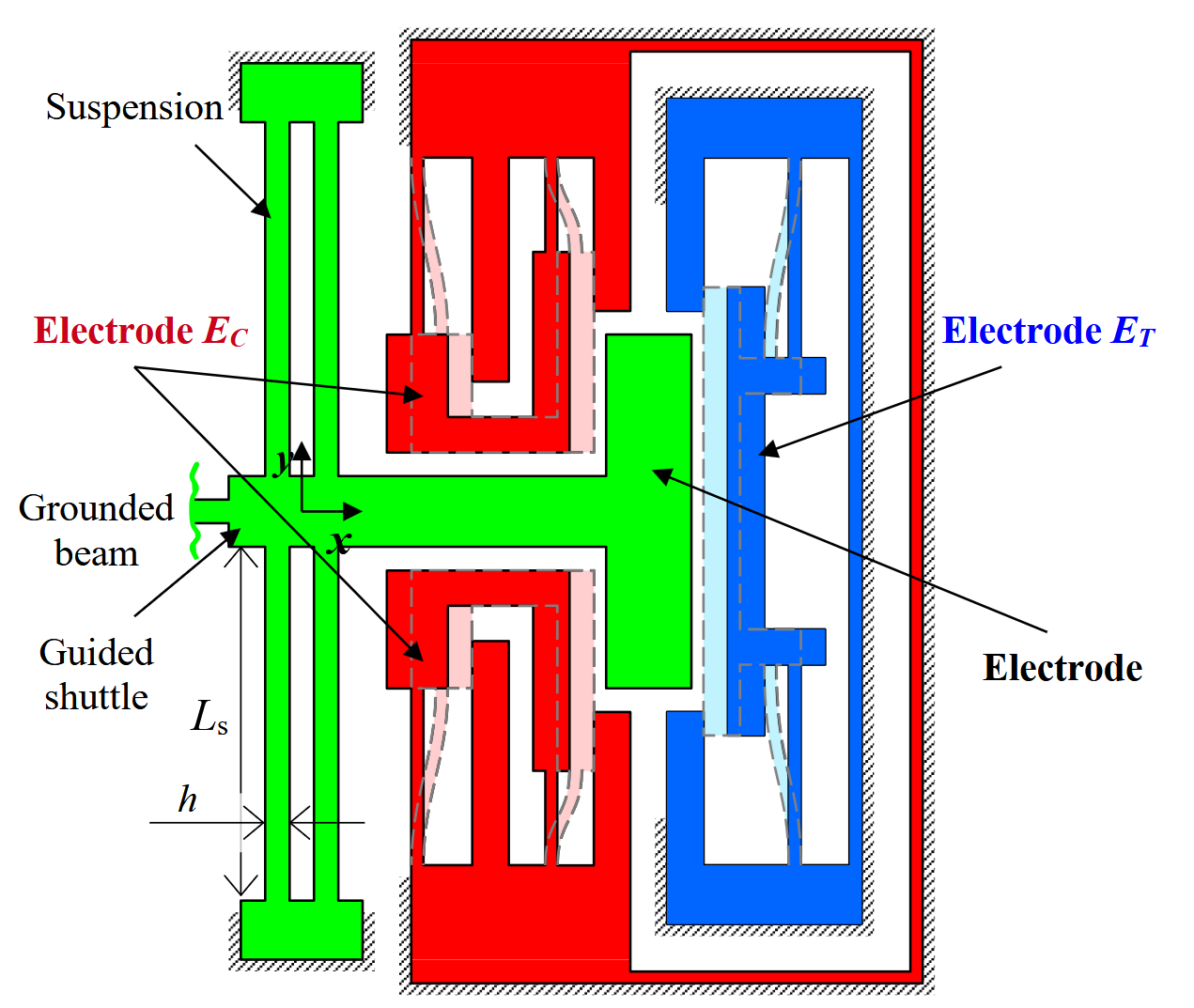
Figure 4.6: Schematic view of a typical test structure: clamped-guided beam, guided shuttle, and electrostatic actuators for applying tension or compression. (Abu-Salih & Elata, 2006).
The guided shuttle is suspended on four flexures. The shuttle is connected to the test beam and to a central electrode used to generate axial load:
- applying voltage
- applying voltage
The suspension stiffness in the axial direction is
while the axial stiffness of the slender beam is
Thus
For the example device with
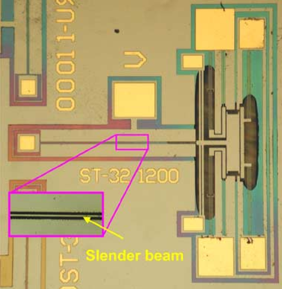
Figure 4.7: Microphoto of a typical test device. The shown clamped-guided beam is
long, and the beam and side gaps are each wide. (Abu-Salih & Elata, 2006).
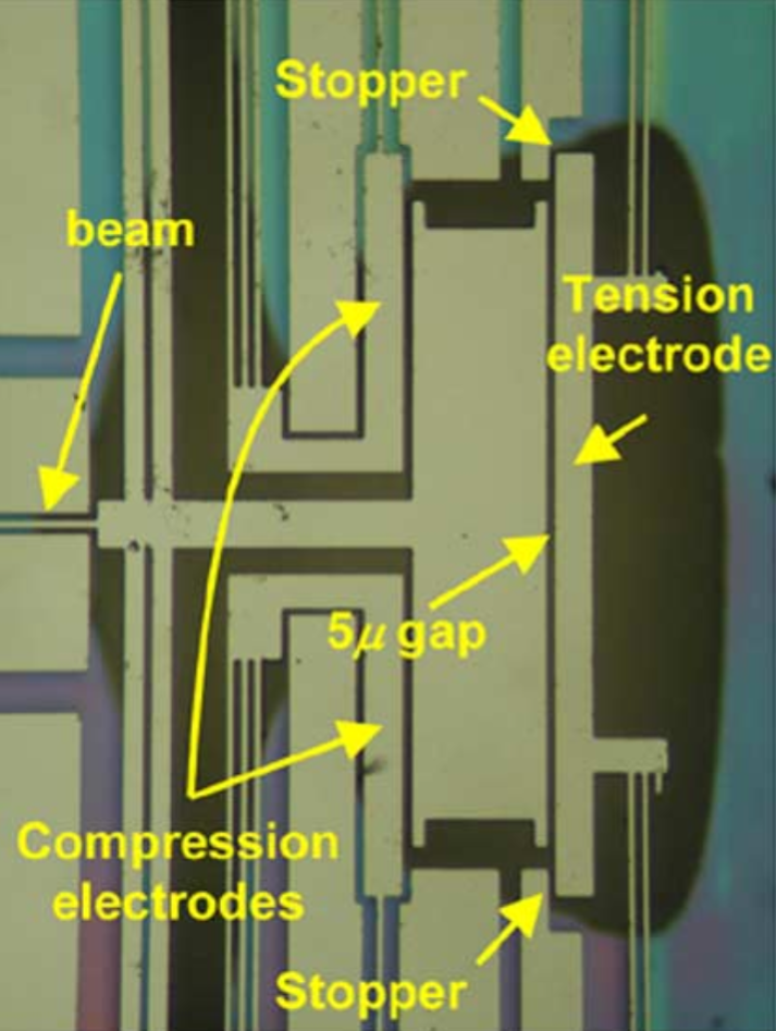
Figure 4.8: Close-up of the tension/compression actuators before engagement. (Abu-Salih & Elata, 2006).
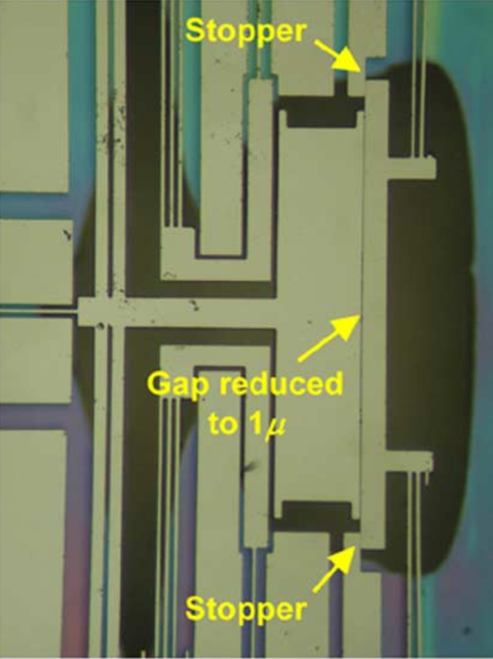
Figure 4.9: Close-up of the tension/compression actuators after engagement. Engagement reduces the gap near the shuttle electrode to about
. (Abu-Salih & Elata, 2006).
The devices were fabricated from single-crystal silicon on SOI wafers using DRIE. The side gap of the EMB beam was
Test beams had lengths
- for
- for
For results, see the paper (Abu-Salih & Elata, 2006).
Consequence for Residual-Stress Measurement
The critical EMB state of a clamped-guided beam with applied axial load is the same as the critical EMB state of a clamped-clamped beam with corresponding internal residual stress. This means the experimental validation also supports the residual-stress measurement method based on a clamped-clamped beam in a symmetric electrostatic field.
In that method, the measured critical voltage is used to infer the residual stress:
- larger tensile stress requires larger EMB voltage;
- smaller compressive stress also requires larger EMB voltage compared with the Euler point;
- both tensile and compressive residual stresses can be measured with one structure over a continuous range.
The 2005 residual-stress paper emphasizes that the structure should be designed so the post-buckling response is unstable. Then the critical event is catastrophic contact with a side electrode and is easy to observe.
Summary
EMB is a two-parameter bifurcation controlled by axial load and voltage. The symmetric electrostatic field adds a destabilizing stiffness term but does not choose a side before instability. The critical states form a curve in
The experiments validated this prediction using clamped-guided silicon beams with electrostatically applied tension or compression. After correcting for fringing fields, the measured EMB voltages agreed with theory to within a few percent, supporting both the clamped-guided EMB model and its use as indirect validation of the residual-stress EMB method.